
Remember the Intel SDK-85? Intel’s single-board “system design kit” for the 8085? Late 70s/early 80s era cutting edge computer hardware. It had a 110 baud teletype (current loop) serial interface. I assembled one back in the day but never used the teletype, only the keyboard/LED onboard control.
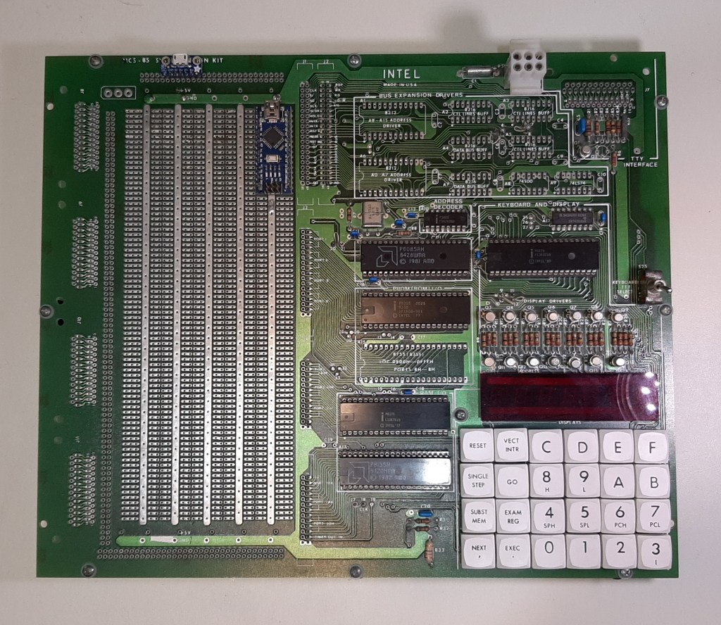
I recently uncovered my old SDK-85 at an archeological dig in my home office and decided to finally try using the serial interface. Problem was I don’t have any compatible hardware that uses the teletype interface, much less that supports data rates as slow as 110 baud (try to select that speed on your i7 Windows 10 system…).
So I decided to use an Arduino to convert from 110 baud to a higher speed USB interface. For two reasons, because I could and because I have a bunch of Arduinos laying around.
This was a fun project since I had to exercise brain cells and low level programming skills that had atrophied over the years (I haven’t written software professionally since the 1990s — management). I encountered some interesting issues resulting from the fact that my Arduino code is full duplex and the SDK-85 is barely half-duplex. Fortunately I had the SDK-85 manual with full assembly source code and schematics to help.
Background
First, some background on the SDK-85 (for information on the Intel 8085 architecture, look here).
The SDK includes the following built-in features (from the manual):
- High-performance [!}, 3 MHz 8085 cpu (1.3 µs instruction cycle)
- Popular 8080A Instruction Set
- Direct Teletypewriter Interface
- Interactive LED Display
- Large Wire-Wrap Area for Custom-Designed Circuit
- System Monitor Software in ROM
The first step I took was to determine how the SDK-85 sends and receives characters. Fortunately the manual includes a listing of the monitor assembly code. Serial data is bit-banged a byte at a time (as expected).
Serial data is sent at 110 baud, or 110 bits per second (bps). That’s 9.1 ms per bit. Each byte of data starts with a START bit, followed by the eight data bits. The SDK doesn’t use a parity bit, so after the data is a STOP bit (really just an idle time at a 0 logic level before the next byte). So each byte takes 10 bit times (minimum) to transmit or receive, 91 ms.
What happens next and how if figured out how the data is really sent and received in Part 2…

Coincidentally, I’m also trying to get a serial interface working again on my old SDK-85. I had a clumsy setup actually working back in 1996 but it won’t play along at the moment. Is there a chance you’ve completed “Part 2” perhaps? – I’d like to see what you ended up with.
LikeLiked by 1 person
Thanks for your comment! Now that I know someone is actually reading this, I’ll get off my butt and finish Part 2.
LikeLike
Only when you’re ready please – no need to rush. One of the attractive things about these old projects is their timelessness 🙂
LikeLiked by 1 person
I recently grabbed the SDK-85 from ebay and working to get it up and running. The keyboard works fine but having RS232 access would help a lot. So… would love to see Part 2 of this article!!
LikeLike
Well now I have a couple of requests for part 2. I’ll do it after the holidays when I have time.
LikeLike
I had my SDK85 fully loaded with all expansion chips / drivers / bus connctors and added programming sockets for the 8755 / 2732 EPROMS. Blasting required 25 volts I recall. I also added RS232 to TTL driver / receiver to talk to an ADM-3A and DEC terminals. Search for SDK-85 System Design Kit Users Manual on archive or bitsavers and you will see the Monitor program listing and schematics.
LikeLike
I’ve been thinking more about this again, and I’m considering a slightly different approach that I’d like to run past you both.
I’ve got a spare Raspberry Pi Zero W 2 which I’m planning on using as not only a TTY/RS-232 interface instead of an Arduino, but as a host for the original development tool set. I’ll use the PiGPIO library on the Pi to handle the 110 baud bit-banging serial communications (https://abyz.me.uk/rpi/pigpio/) along with a 3.3V 5V level-shifter. But the real enticement is that running DOSBox or DOSEmu on the Pi will allow me to run the original intel development tools, including the ISIS-II emulator which is required to run the original assembler (https://www.intel-vintage.info/intelsofware.htm). I was initially thinking of hacking together an assembler in Python but that’s unnecessary now and would’ve been a major detour anyway (no need to reinvent the wheel, again).
So far I’ve installed DOSBox on the Pi and then into that the ISIS-II emulator and assembler and that’s all looking good. I’ve been able to assemble the complete SDK-85 Monitor source code using that setup which gives me confidence. Unfortunately I’ve been moving house and along with other distractions, I haven’t been able to do more than that except purchase the level shifter. Some time in the New Year though, I’m going to mount the Pi and level shifter into a spare area on the SDK-85 board and get the bit-banging operating. After that I’m thinking of supplementing the on-board SDK-85 Monitor with a separate EEPROM to handle downloading of assembled code, and then executing it. This way, I can preserve the original SDK-85 but just augment it with add-ons.
Interested to hear your thoughts … and all the best wishes for the season.
LikeLiked by 1 person
Hi Steve,
I like your plan, it’s certainly more ambitious than what I did!
The Pi Zero should be more than powerful enough to do what you want.
I’m looking forward to seeing how it all comes out. Please let us know!
Thanks,
Anson
LikeLike